Specification of ZF transmissions
Lay Out (1) ZF transmission 4WG-190/210
![]()
1. Clutch Shaft “ KR”
2. Power Take Off Coaxial
3. Clutch Shaft “KV”
4. Clutch Shaft “K2”
5. Clutch Shaft “K3”
6. Output flange Rear
7. Output flange Converter
8. Output shaft
9. Transmission Pump
10. Input Flange
11. Converter
12. Transmitter for Engine speed
13. Clutch Shaft “K4”
14. Converter Relief V/V
15. Clutch Shaft “K1”
Lay Out Front view (2) ZF transmission 4WG-190/210
![]()
1. Lifting plug
2. Drive flange
3. Transmission suspension
4. Attachment for Emergency Steering Pump
5. Model I/D
6. Output Flange Converter Side
7. Oil Drain Plug
8. Attachment for oil filter pipe
9. Oil Dipstick
Lay Out Side view (3) ZF transmission 4WG-190/ 210
![]()
1. Driving Flange
2. Cover
3. Converter Bell Housing
4. Breather
5. Transmission Case Cover
6. Filter head & Alarm Switch
7. Fine Filter
8. Oil Dipstick
9. Output Flange-Rear
10. Oil Drain Plug
11. Out Flange - Front
12.Transmission Case
Lay Out Rear view (4) ZF transmission 4WG-190/210
![]()
1. Lifting Lugs
2. Power Take Off
3. Electro- Hydraulic Control
4. Return port (Option-Parking brake)
5. Oil Dipstick
6. Transmission Suspension
7. Output Flange
8. Fine Filter
9. Filter Head & Alarm Switch
10. System Pressure Port (Option- Parking Brake)
Measuring Point (1) ZF transmission 4WG-190/210
![]()
21. Inductive transmitter : Turbine
34. Speed Sensor : Output and Speedmeter
47.Inductive transmitter : Central Gear Train
48. Inductive transmitter : Engine
Measuring Point (2) ZF transmission 4WG-190 /210
![]()
|
Driving Direction |
Speed |
Y1 |
Y2 |
Y3 |
Y4 |
Y5 |
Y6 |
Engaged |
|
Forward |
1st |
|
|
* |
|
* |
|
K1,KV |
|
|
2nd |
|
|
|
|
* |
* |
KV,K2 |
|
|
3rd |
|
|
|
* |
* |
|
KV,K2 |
|
|
4th |
* |
|
|
* |
|
|
K4,K3 |
|
Reverse |
1st |
|
* |
* |
|
|
|
KR,K1 |
|
|
2nd |
|
* |
|
|
|
* |
KR,K2 |
|
|
3rd |
|
* |
|
* |
|
|
KR,K3 |
|
Neutral |
|
|
|
|
|
|
|
|
|
Related Clutch |
|
K4 |
KR |
K1 |
K3 |
KV |
K2 |
|
|
Location |
|
F |
E |
D |
C |
B |
A |
|
|
Measuring Point |
|
60 |
55 |
56 |
58 |
53 |
57 |
|
|
System Pressure (bar) |
|
16±2 |
16±2 |
16±2 |
16±2 |
16±2 |
16±2 |
|
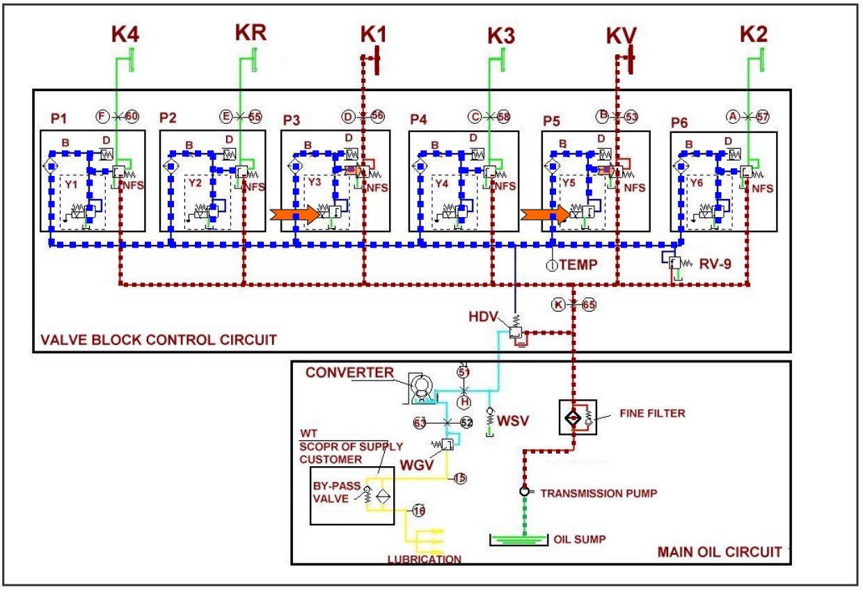
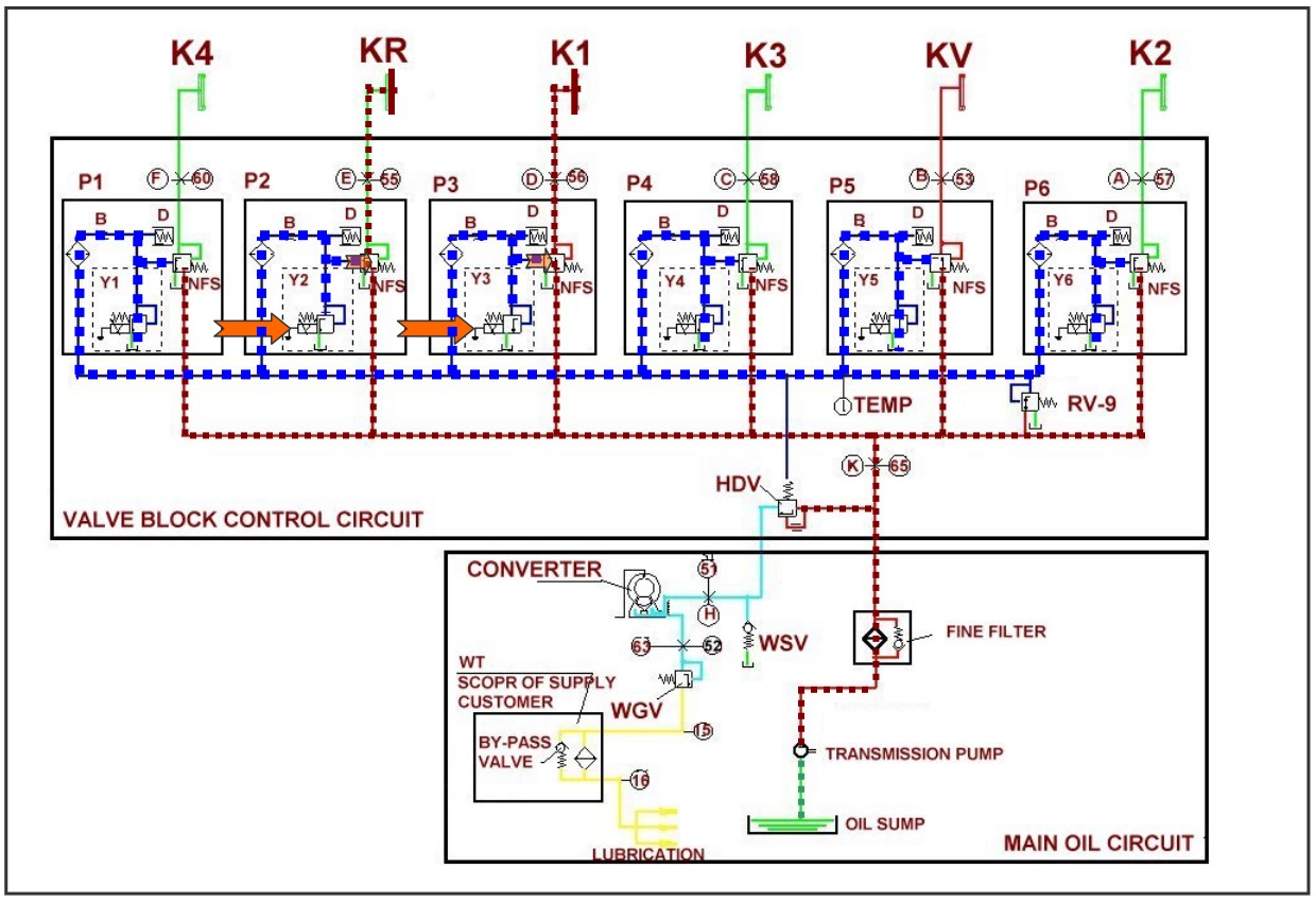
Oil Circulation (System Pressure) of ZF transmission
![]()
WGV : Converter Back Pressure Valve 3~5 bar
WSV : Converter Relief Valve 11 bar
HDV : System pressure 16 bar
RV-9 : Pressure Reducing Valve 9 bar
NFS : Follow-on Slide
D : Oscillation Damper
P : Proportional Valve Clutch
Y : Pressure Regulator
B : Orifice
Temp : Temperature Sensor ( RV-9 Pressure measuring after being detached)
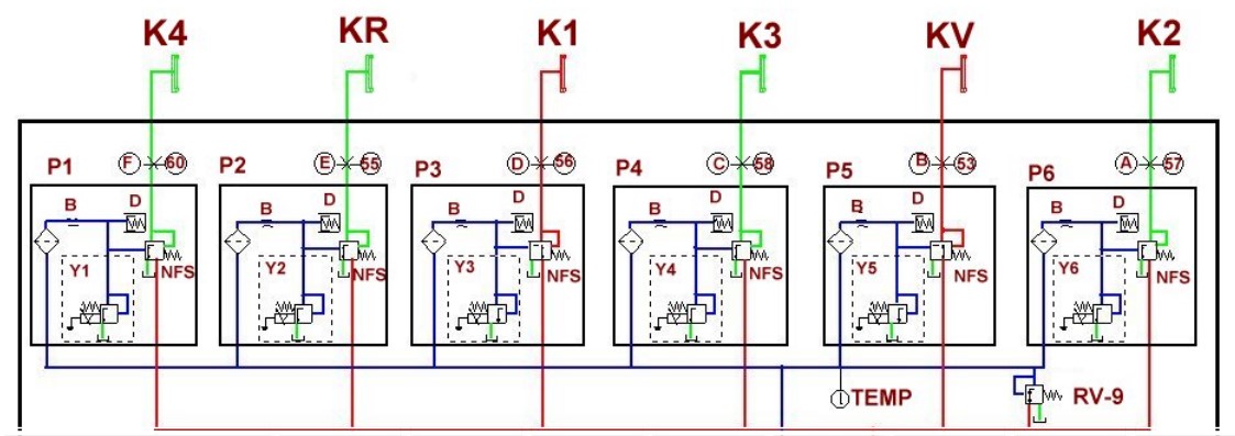
Working of Proportional Valve
![]()
Oil Circulation - Neutral Position (System Pressure)
.jpg)
Oil Circulation - Neutral Position (Pilot Pressure)
.jpg)
Oil Circulation - Neutral Position (T/Q Converter)
.jpg)
Oil Circulation - Forward 1st
Oil Circulation - Reverse 1st
Engaged EPPR Valve Summary
|
Driving Direction |
Speed |
Y1 |
Y2 |
Y3 |
Y4 |
Y5 |
Y6 |
Engaged |
|
Forward |
1st |
|
|
* |
|
* |
|
K1,KV |
|
|
2nd |
|
|
|
|
* |
* |
KV,K2 |
|
|
3rd |
|
|
|
* |
* |
|
K3,KV |
|
|
4th |
* |
|
|
* |
|
|
K4,K3 |
|
Reverse |
1st |
|
* |
* |
|
|
|
KR,K1 |
|
|
2nd |
|
* |
|
|
|
* |
KR,K2 |
|
|
3rd |
|
* |
|
* |
|
|
KR,K3 |
|
Neutral |
|
|
|
|
|
|
|
|
|
Related Clutch |
|
K4 |
KR |
K1 |
K3 |
KV |
K2 |
|
Oil Circulation - Hydraulic Control (1)
.jpg)
Oil Circulation - Hydraulic Control (2)
.jpg)
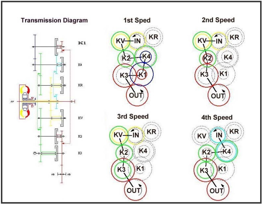
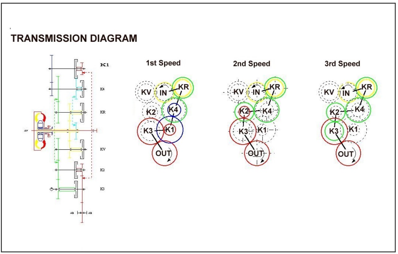
Gear Schema - ZF transmission 4WG190/210
![]()
KV :Clutch Forward KR: Clutch Reverse
K1: Clutch 1st Speed K2: Clutch 2nd Speed
K3: Clutch 3rd Speed K4: Clutch 4th Speed
IN : Input Out : Out Put
Power Flow - Forward 4WG 190/210
Power flow - Reverse 4WG190/210
T/M Electric Control System
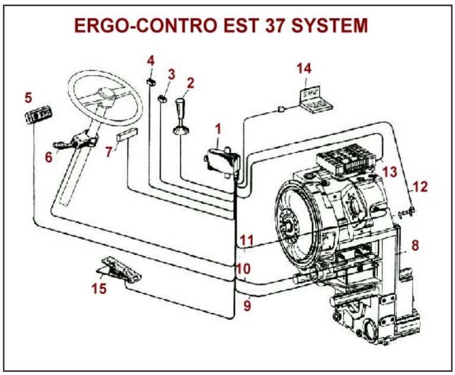
1. EST 37 CONTROL UNIT
2. KICKDOWN SWITCH
3. T/M CUT OFF SWITCH
4. AUTO SELECT SWITCH
5. DISPLAY
6. DW-3 CONTROLLER INCLUDING KICK DOWN SWITCH
7. SUPPLY SYSTEM CONNECTION
8. TRANSMISSION
9. CENTRAL GEAR TRAIN SPEED SENSOR
10. TURBINE SPEED SENSOR
11. ENGINE SPEED SENSOR
12. OUTPUT SPEED SENSOR
13. CABLE ( TO ELECTRO HYDRAULIC CONTROL UNIT)
14.DIAGNOSIS LAPTOP (OPTION)
15. BRAKE PRESSURE SENSOR
Description of Components
Pressure Regulator in Transmission Control Block