There are 3 main types of Kawasaki pump applied on hydraulic excavators:
1. K5V80
2. K3V112
3. K5V140
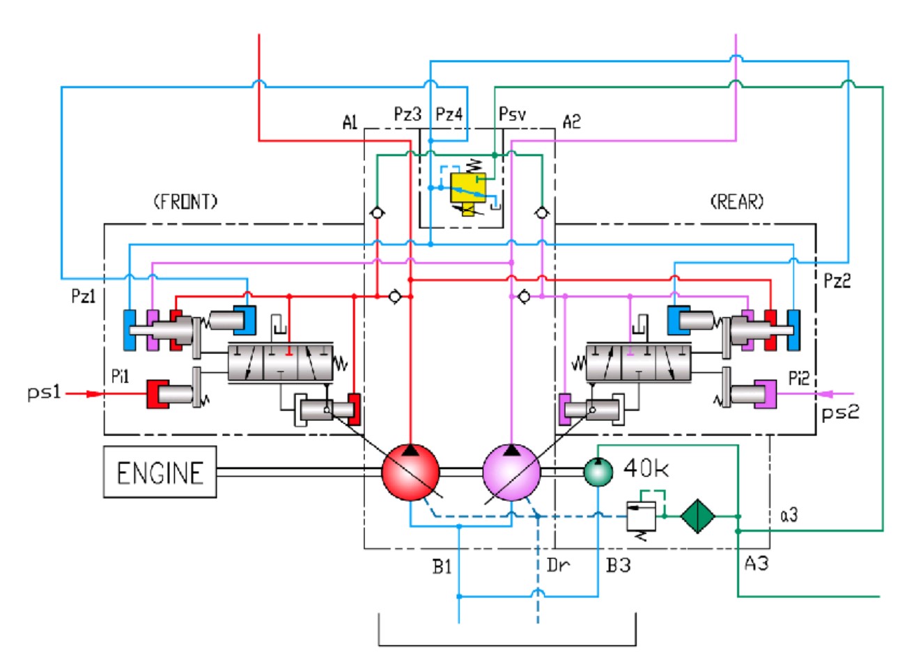
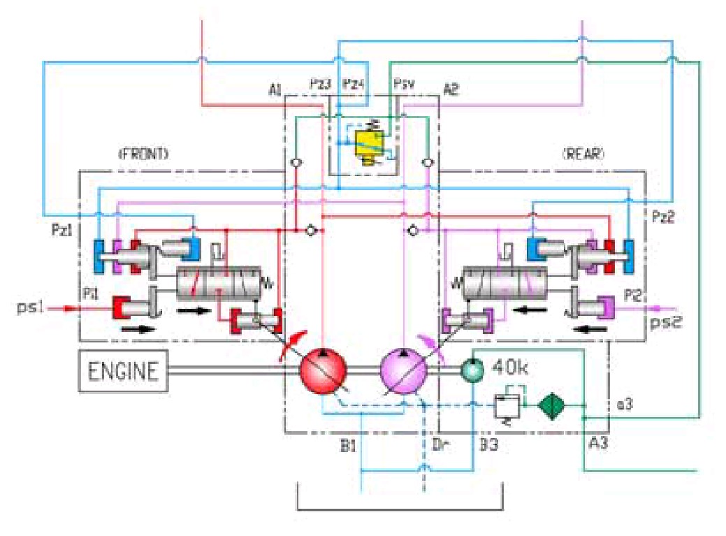
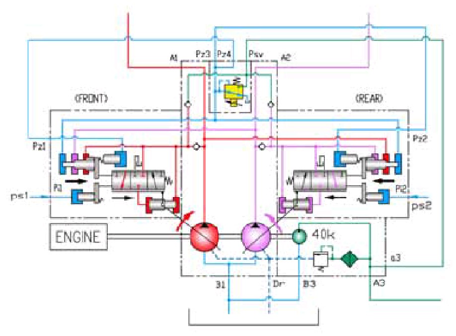
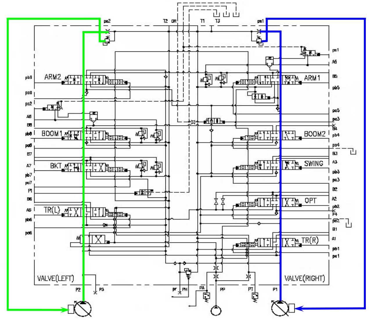
K3V112 schematic hydraulic pump
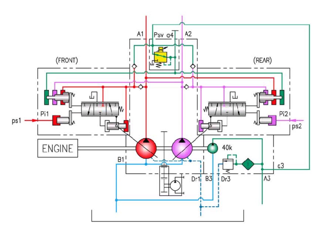
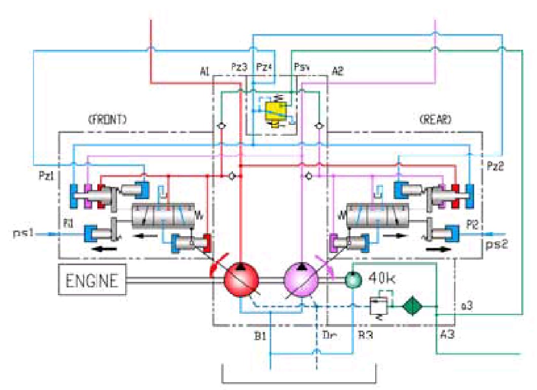
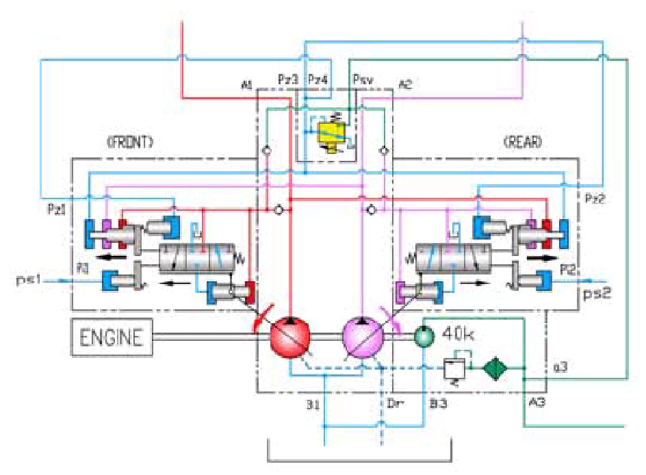
K5V140 schematic hydraulic pump
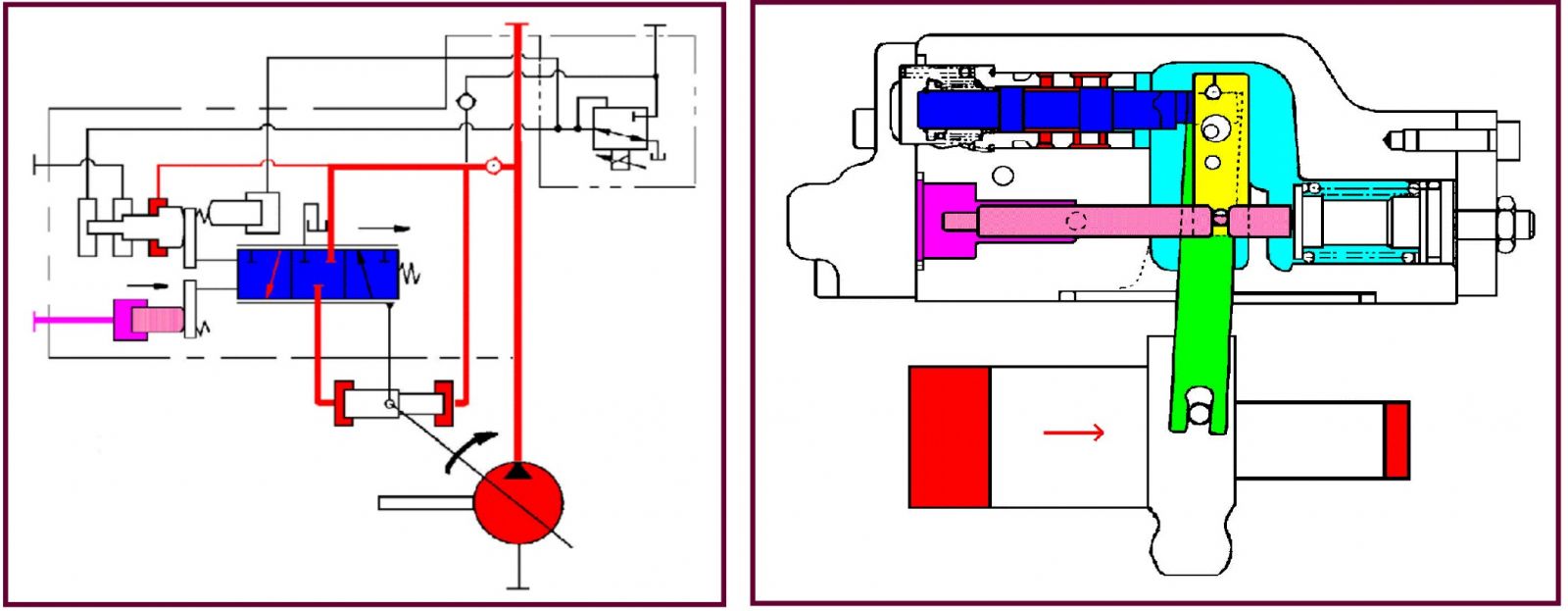
Flow Control (Decrease flow)
Control valve spools are neutral, High negacon pressure comes up to pilot piston.
The pilot piston makes spool move to decrease oil flow.
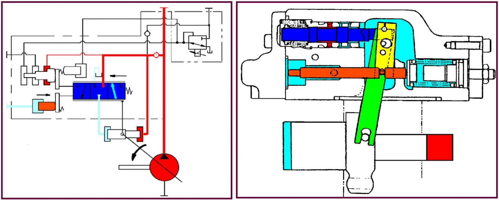
Flow Control (Increase flow)
When move spools, Low negacon pressure comes up to pilot piston.
The pilot piston makes spool move to increase oil flow.
Power Control (Decrease flow)
System pressure is getting increase, compen piston is moved.
The compen piston makes control spool move to decrease oil flow.
Power Control (Increase flow)
System pressure is getting decrease, compen piston is moved.
The compen piston makes control spool move to increase oil flow.
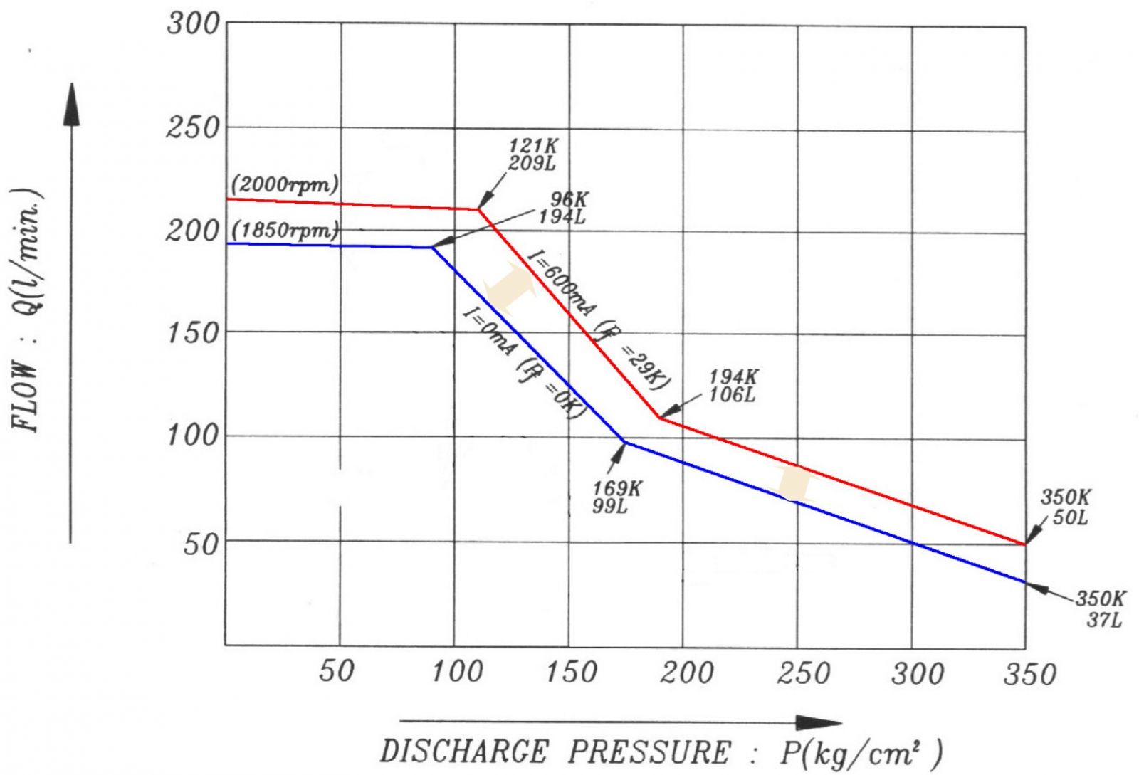
Power shift curve (Power Mode)
K3V112 Pump
.jpg)
K5V140 Pump
Power Shift (K3V112 pump)
Standard mode : 0mA (0 bar)
Power mode : 600mA (29 bar)
Power Shift (K5V140 pump)
Standard mode : 0mA (18 bar)
Power mode : 600mA (0 bar)
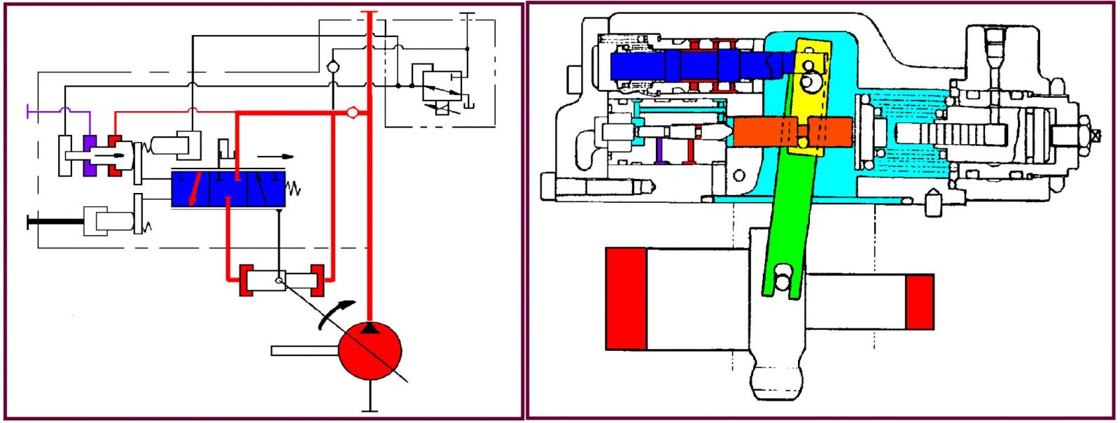
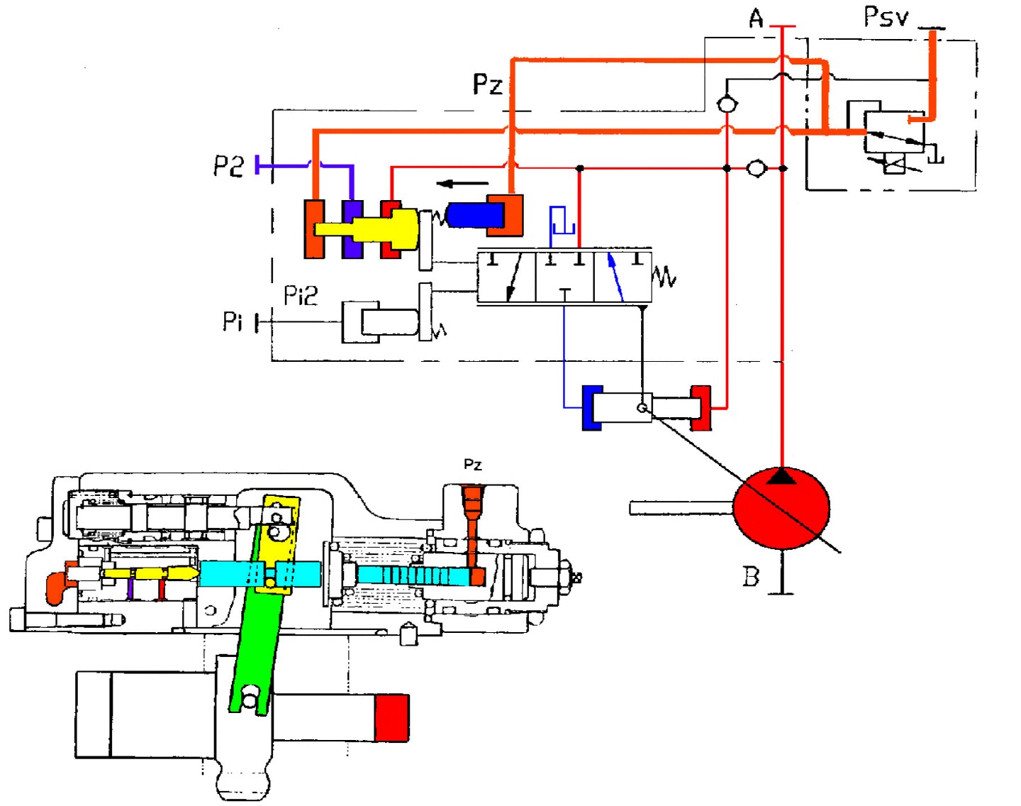
Inner Structure of Hydraulic Pump
Body of hydraulic pump
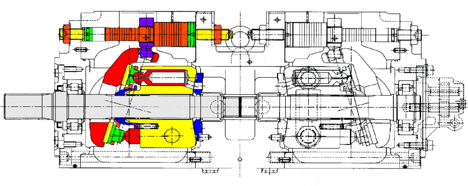
▷ Two variable displacement axial piston pumps connected in series
▷ A geartype pilot pump mounted on the second main pump
▷ Flow output controled by regulators on each pump
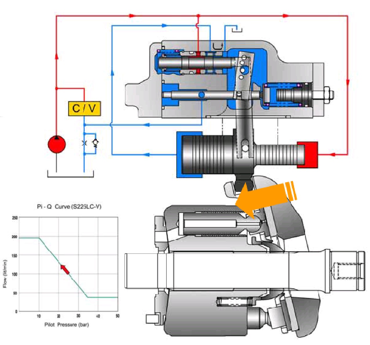
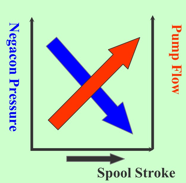
Regulator (Negacon Control)
Regulator consists of the positive flow control, constant horse power control and variable horse power control function.
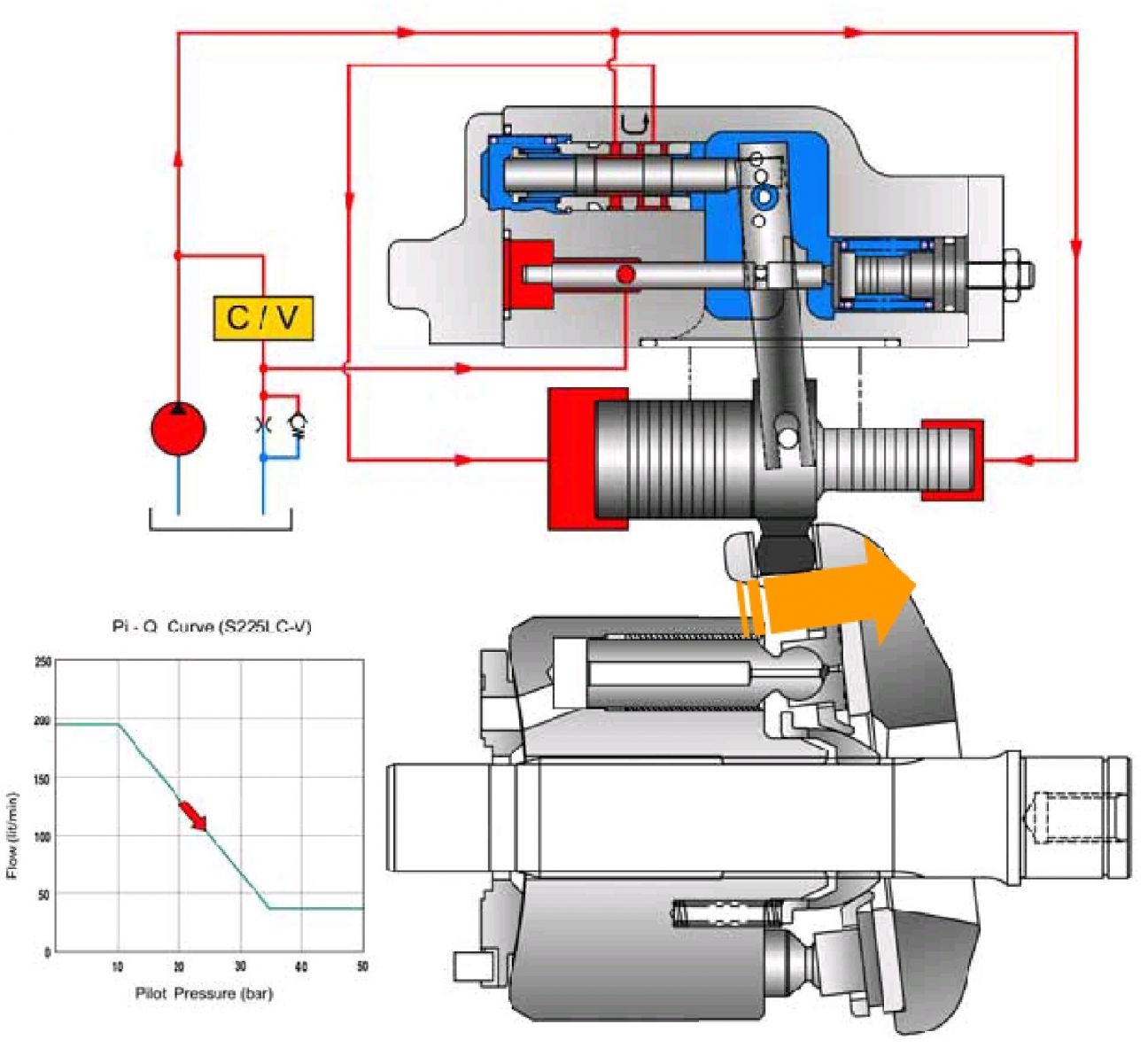
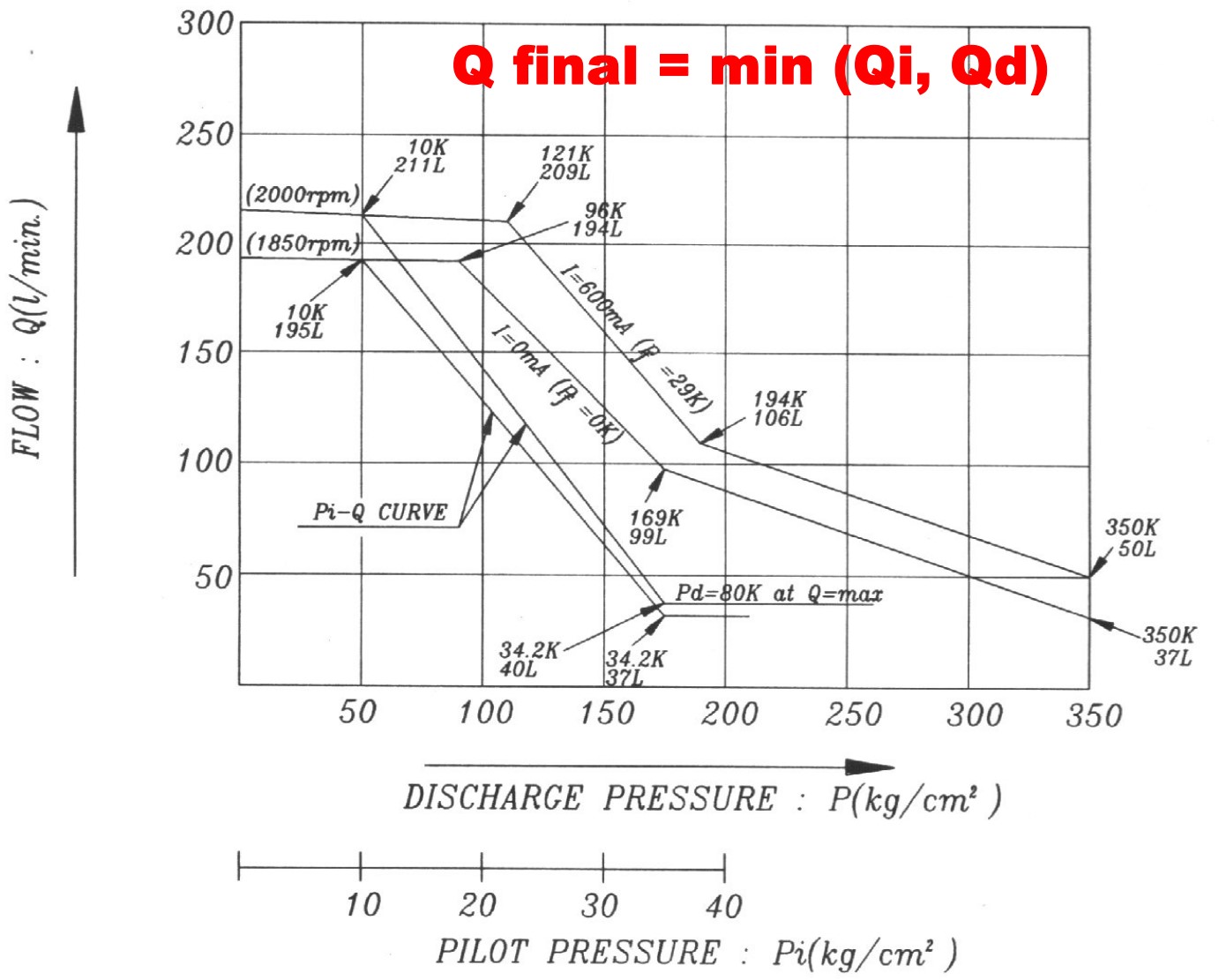
(1) Positive flow control
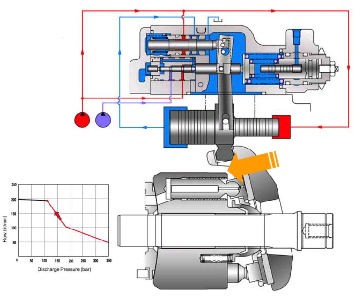
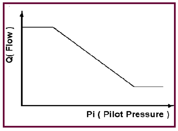
By changing the pilot pressure Pi, the pump tilting angle (delivery flow) is regulated arbitrarily, as shown in the figure.
This regulator is of the positive flow control in which the delivery flow Q increases as the pilot pressure Pi rises. With this mechanism, when the pilot pressure corresponding to the flow required for the work is commanded, the pump discharges the required flow only, and so it does not consume the power uselessly.
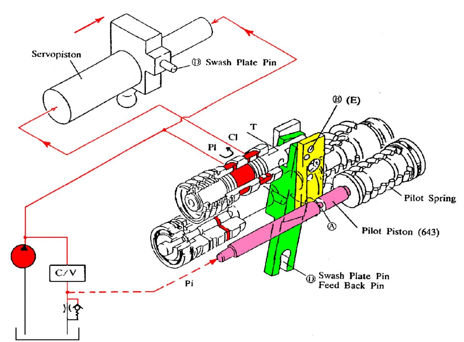
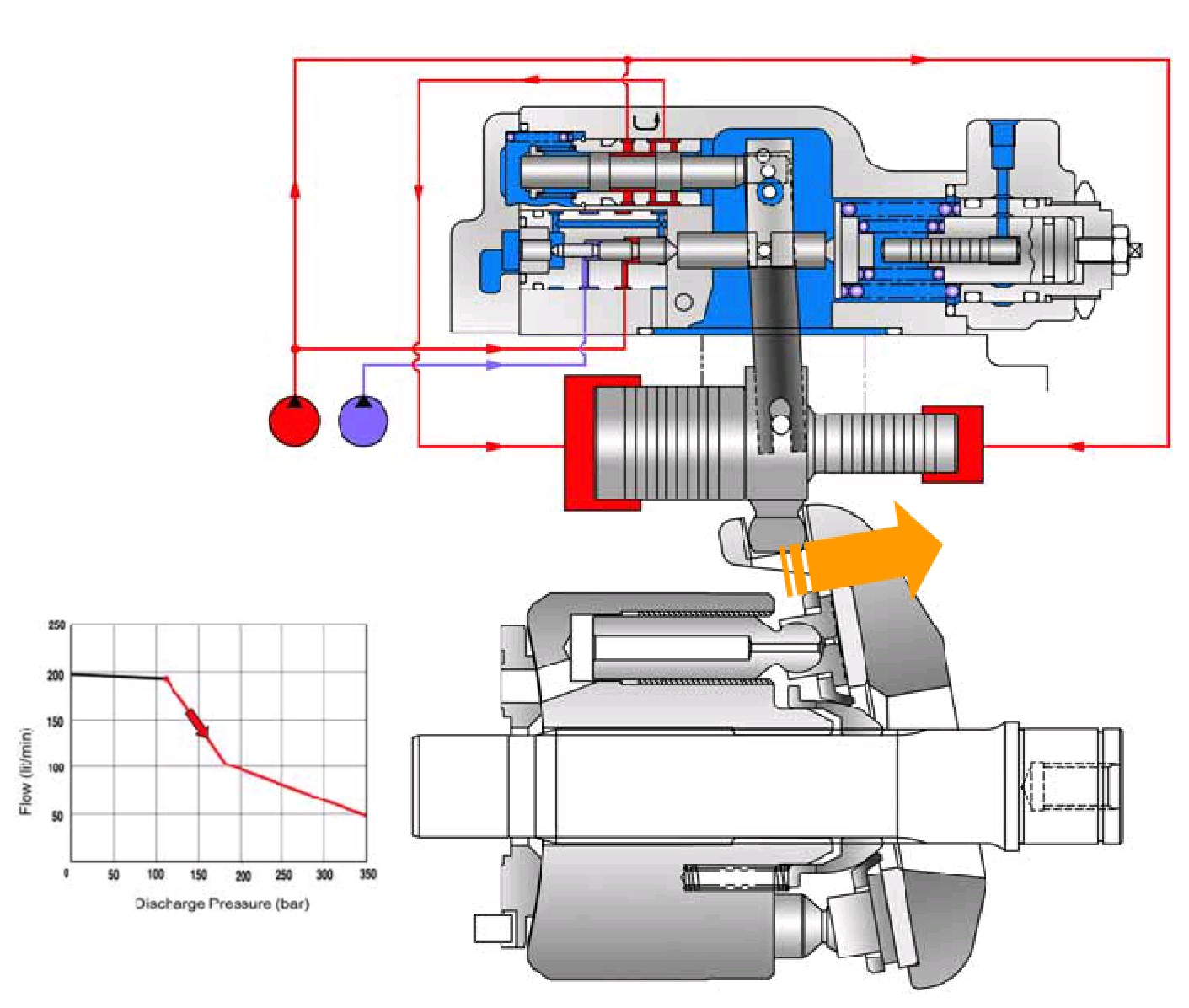
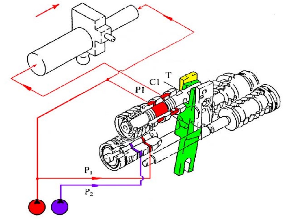
Regulator (Power Control)
Negacon Control
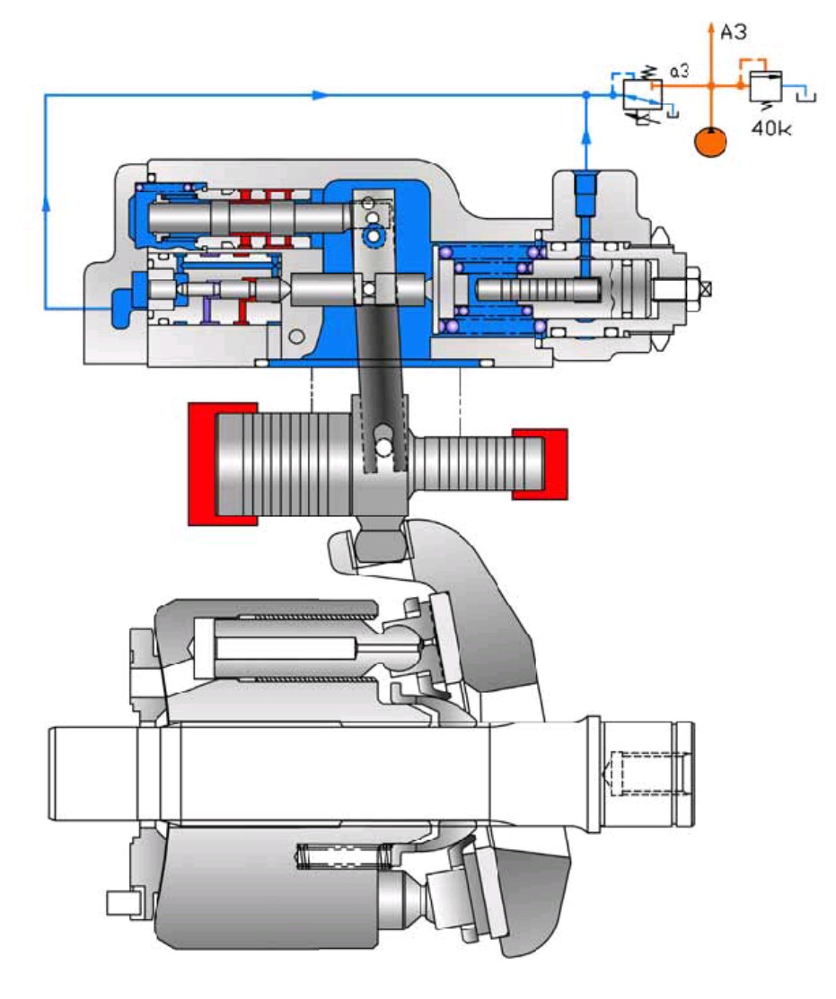
▶ Negacon Pressure
▶ Flow Decrease Circuit
As the pilot pressure Pi decreases, the pilot piston (643) moves to the left by the action of the pilot spring (646) and causes lever 2 (613) to rotate around the fulcrum of point G. Since the pin (897) is pressed against the large hole section (C) of lever 2 by the action of the return spring (654) via the spool (652), pin (874), and feedback lever (611), the feedback lever rotates around the fulcrum of point D as lever 2 rotates, and shifts the spool to the right.
The movement of the spool causes the delivery pressure P1 to connect to port CL through the spool and to be admitted to the large diameter section of the servo piston. The delivery pressure P1 that is constantly admitted to the small diameter section of the servo piston moves the servo piston to the right due to the area difference, resulting in decrease of the tilting angle.
When the servo piston moves to the right, point D also moves to the right. The spool is fitted with the return spring (654) and is tensioned to the left at all times, and so the pin (897) is pressed against the large hole section (C) of lever 2.
Therefore, as point D moves, the feedback lever rotates around the fulcrum of point C, and the spoolisshiftedtotheleft. Thiscausestheopeningbetweenthesleeve(651)andspool(652)to close slowly, and the servo piston comes to a complete stop when it closes completely.
▷ High Negacon Pressure (Pi) => Low Oil Flow (Qi)
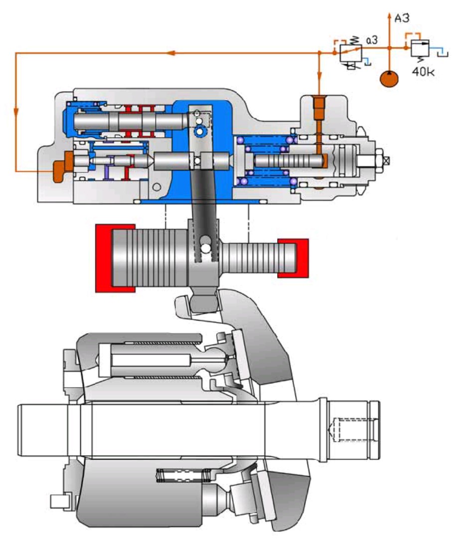
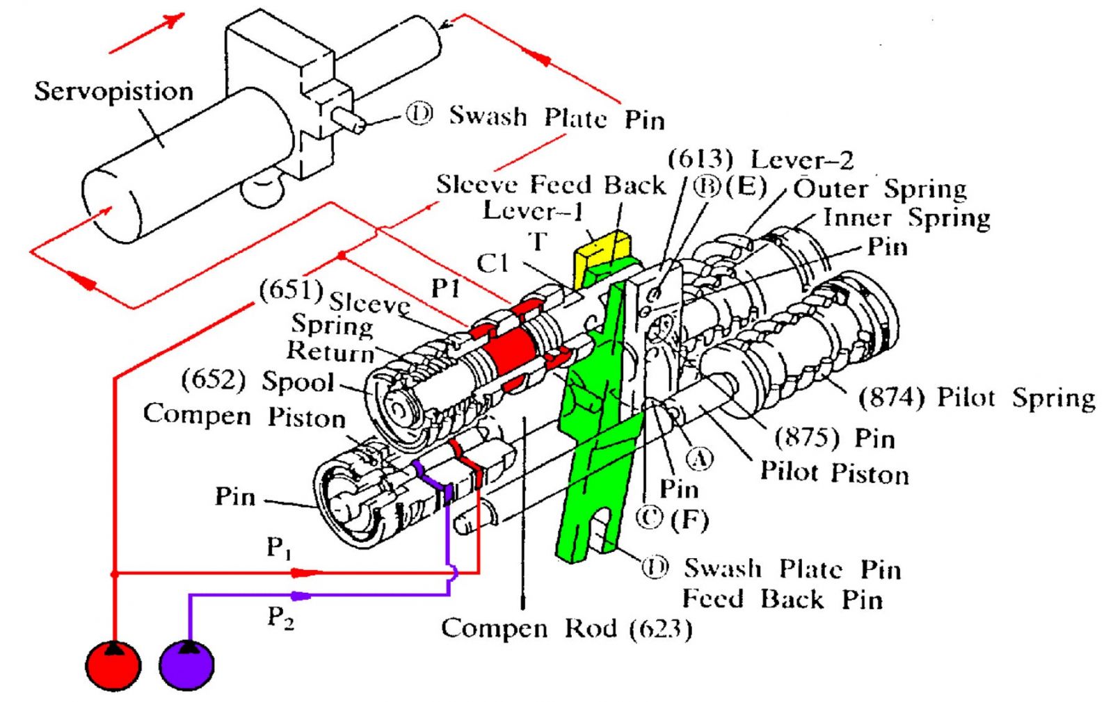
▶ Flow Increase Circuit
As the pilot pressure Pi rises, the pilot piston (643) moves to the right to a position where the force of the pilot spring (646) balances with the hydraulic force.
The groove (A) in the pilot piston is fitted with the pin (875) that is fixed to lever 2 (613). Therefore, when the pilot piston moves, lever 2 rotates around the fulcrum of point G [fixed by the fulcrum plug (614) and pin (875)]. Since the large hole section (C) of lever 2 contains a protruding pin (897) fixed to the feedback lever (611), the pin (897) moves to the left as lever 2 rotates.
Port CL opens a way to the tank port as the spool moves. This deprives the large diameter section of the servo piston of pressure, and shifts the servo piston to the left by the discharge pressure P1 in the small diameter section, resulting in an increase in the flow rate.
As the servo piston moves, point D also moves to the left, the feedback lever rotates around the fulcrum of point C, and the spool moves to the right till the opening between the spool and sleeve is closed.
▷ Low Negacon Pressure (Pi) => High Oil Flow (Qi)
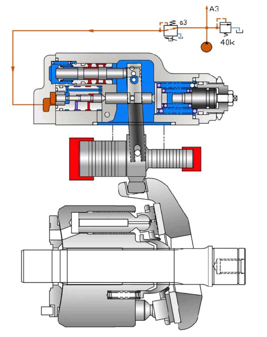
Power Control
▶Overload Protection
▷ POWER pump = (Pd * Q )/450 where Pd in bar, Q in lpm
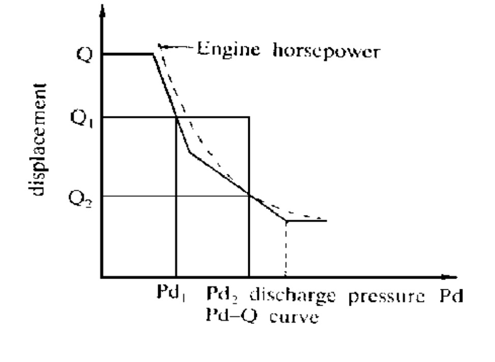
▷ POWER pump ≤ POWER engine
▷ Cross Over Power Control (or Summation Power Control)
▶ Overload Protection Circuit
▷ High Average Pressure (Pd) => Low Oil Flow (Qd)
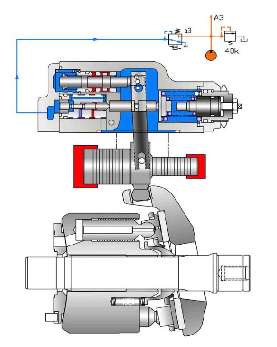
Final Oil Flow Determination
▶ Final Q determined by Regulator
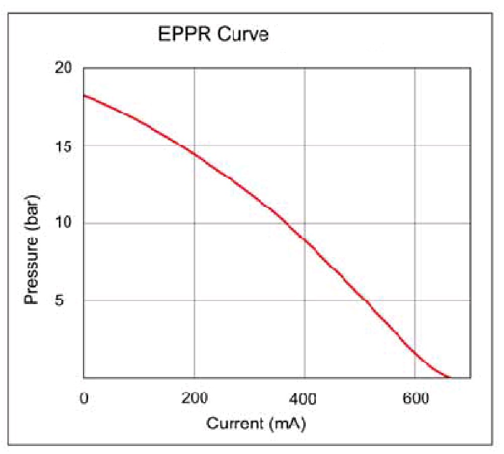
Powershift Control
▶ Concept of Powershift Control
▶Operating of Powershift Control
▶Characteristic of powershift valve
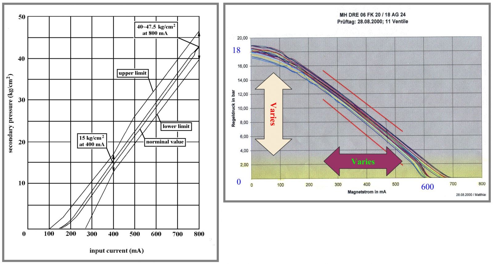
▷ ▷ Reference Only
▷ ▷ The characteristic differs as per pump model.
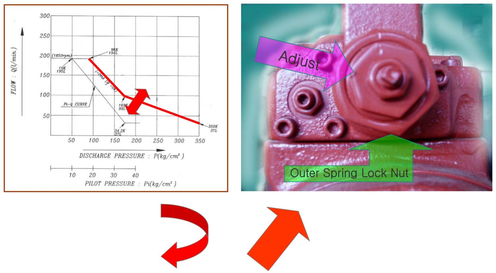
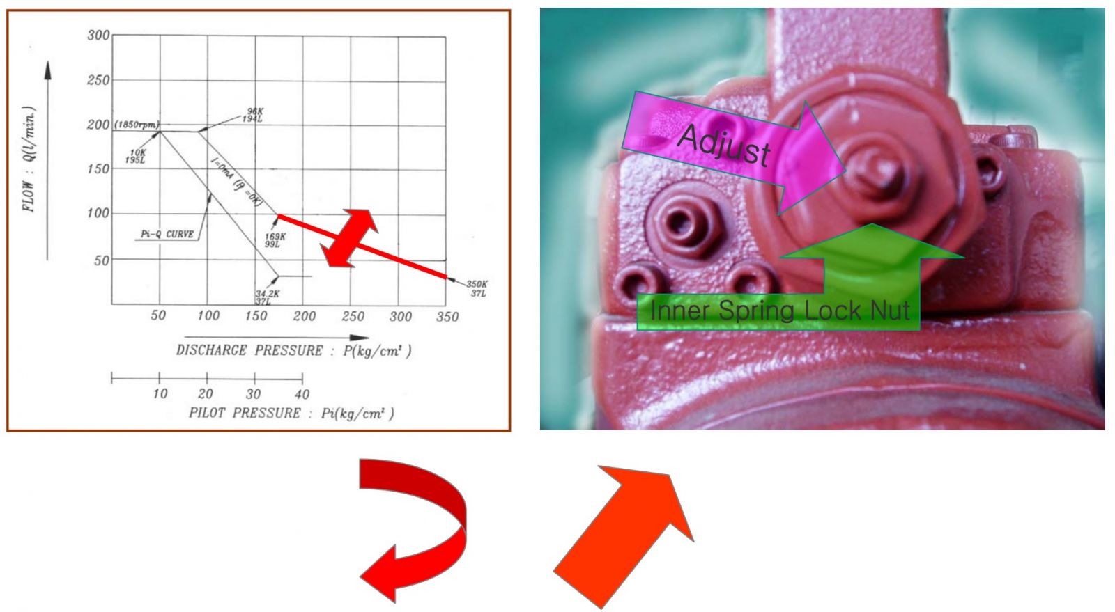
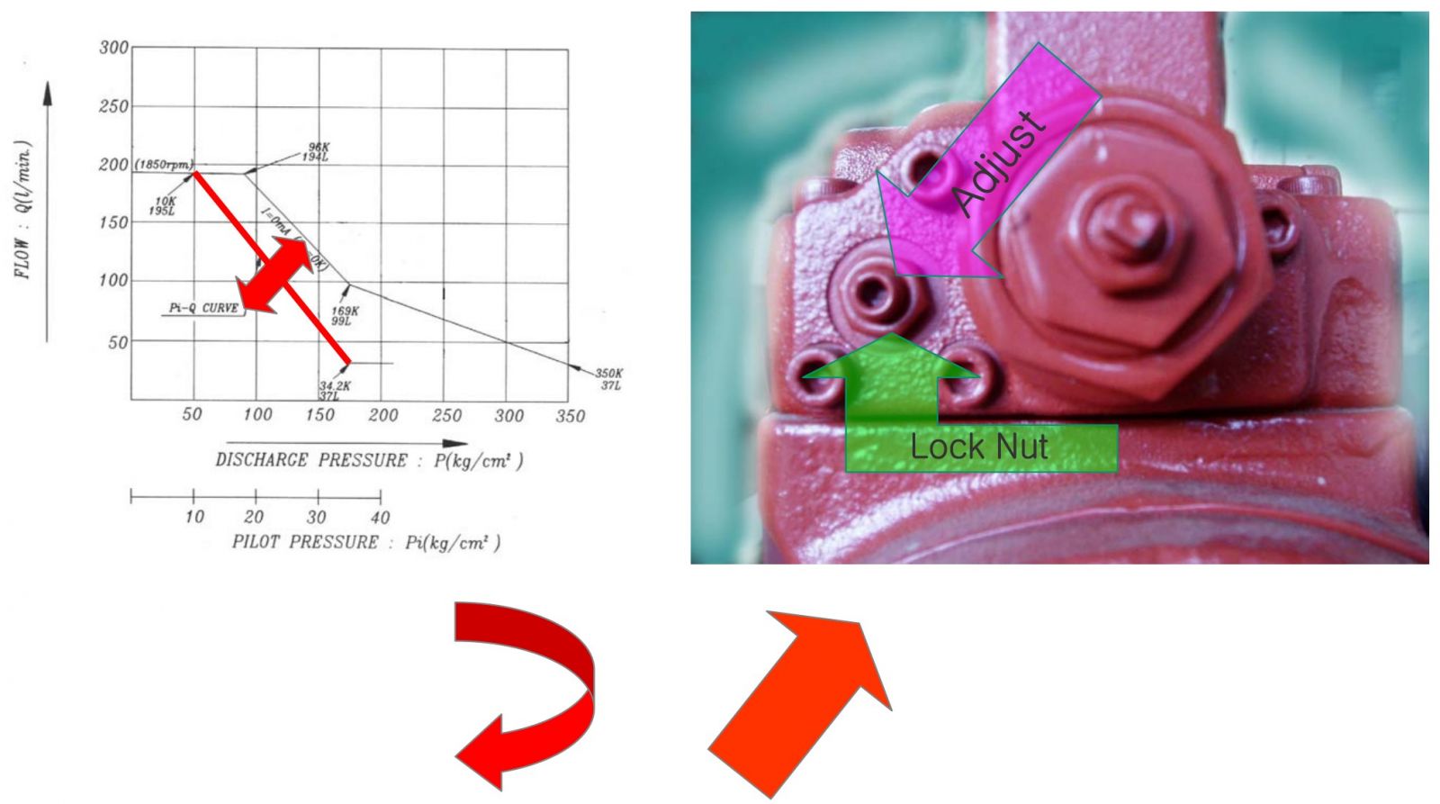
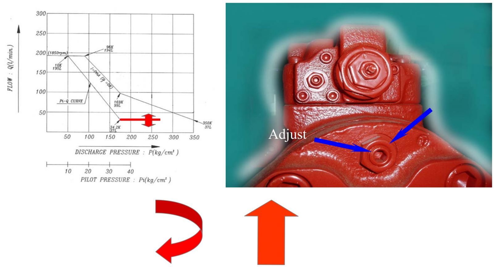
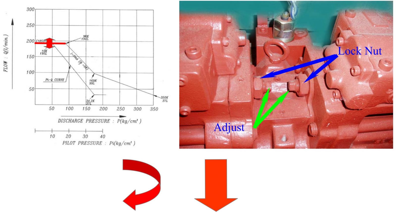
Adjustment of hydraulic pump
The flow control characteristic can be adjusted with the adjusting screw.
Adjust it by loosening the hexagon nut (801) and by tightening (or loosening) the hexagonal socket head screw (924). Tightening the screw shifts the control chart to the right as shown in the figure
▶ Input Power – Outer Spring of Power control
▶ Input Power – Inner Spring of Power control
▶ Negacon Control
▶ Minimum Discharge Flow
▶ Maxmum Discharge Flow
The list of Hyundai hydraulic pumps available to supply.
FUNCTION
MAIN PUMP
The pumps may classified roughly into the rotary group performing a rotary motion and working as the major part of the whole pump function: the swash plate group that varies the delivery rates: and the valve cover group that changes over oil suction and discharge.
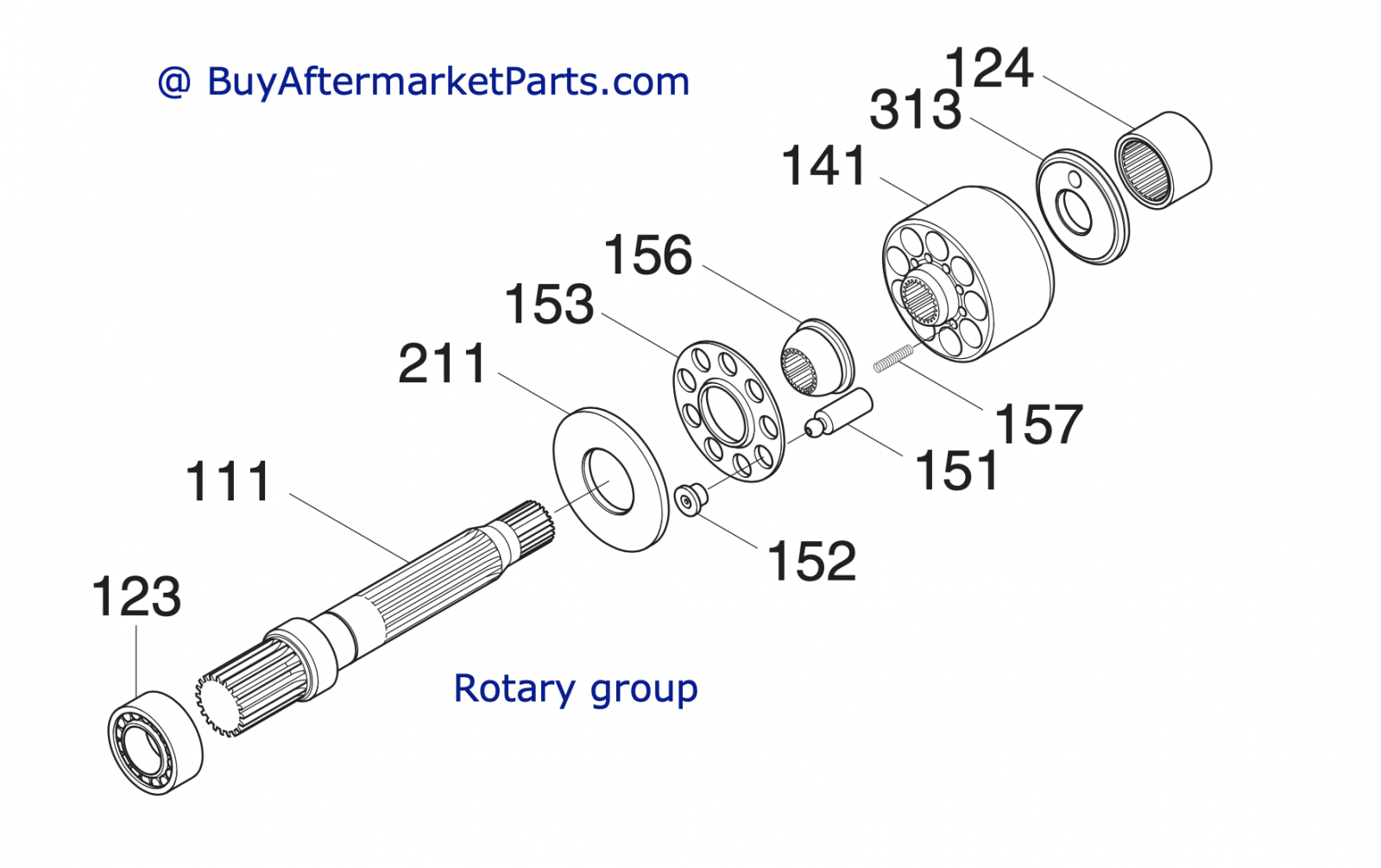
(1) Rotary group
The rotary group consists of drive shaft (F) (111), cylinder block (141), piston shoes (151,152), set plate (153), spherical bushing (156) and cylinder spring (157). The drive shaft is supported by bearing (123,124) at its both ends.
The shoe is caulked to the piston to from a spherical coupling. It has a pocket to relieve thrust force generated by loading pressure and the take hydraulic balance so that it slides lightly over the shoe plate (211). The sub group composed by a piston and a shoe is pressed against the shoe plate by the action of the cylinder spring via a retainer and a spherical bush. Similarly, the cylinder block is pressed against valve plate (313) by the action of the cylinder spring.
(2) Swash plate group
The swash plate group consists of swash plate (212), shoe plate (211), swash plate support (251), tilting bush (214), tilting pin (531) and servo piston (532).
The swash plate is a cylindrical part formed on the opposite side of the sliding surface of the shoe and is supported by the swash support.
If the servo piston moves to the right and left as hydraulic force controlled by the regulator is admitted to hydraulic chamber located on both sides of the servo piston, the swash plate slides over the swash plate support via the spherical part of the tilting pin to change the tilting angle.

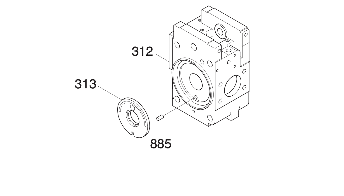
(3) Valve block group
The valve block group consists of valve block (312), valve plate (313) and valve plate pin(885).
The valve plate having two melon-shaped ports is fixed to the valve block and feeds and collects oil to and from the cylinder block.
The oil changed over by the valve plate is connected to an external pipeline by way of the valve block.
Now, if the drive shaft is driven by a prime mover (electric motor, engine, etc), it rotates the cylinder block via a spline linkage at the same time. If the swash plate is tilted as in Fig (previous page) the pistons arranged in the cylinder block make a reciprocating motion with respect to the cylinder block, while they revolve with the cylinder block.
If you pay attention to a single piston, it performs a motion away from the valve plate (oil sucking process) within 180 degrees, and makes a motion towards the valve plate (or oil discharging process) in the rest of 180 degrees. When the swash plate has a tilting angle of zero, the piston makes no stroke and discharges no oil.